Guide OS (1): A Guide to Developing an 64-Bit Operating System on x86
1991 Words
Operating Systems OSDev X86 GuideOS
Tip: you can click on the GuideOS tag above to see all posts in this series.
Code download for this tutorial can be found here
https://github.com/Codetector1374/GuideOS/releases/tag/checkpoint1-rev1
Introduction
OS Development is often thought as a daunting topic, partially because it is complicated, but also due to leaving the conformt of a “hosted” environment that most students are used to. So before we dive right into the builidng our first operating system from scratch, let’s go over the steps that we need to take in order to get our own OS up and running.
The first step would be setup a project that can produce a “freestanding” binary.
Let’s say when you compile a C program with gcc on Linux, you are compiling and
linking not only your code, but together with some runtime libraries that is provided
by the operating system (Linux in this case) to help your program with various
functions such as initialization, printing, reading from input, etc. Since we are
going to be writing an operating system, we will not have access to these functions.
We will need to create a binary without linking against these libraries. Such binary
is often referred to as a “freestanding” binary.
Then we will need to write some x86 boostrap code that helps us setup for kernel execution. This is needed because of a lot of legacy issue that resulted in modern x86 process still boots up in “real mode” that emulates an 8086, which has only 16-bit regisers and access to the first 1 Megabyte of system memory. We want to be operating in 64-bit mode, so we will need to write code to transition ourselve into that mode of operation.
Once we have that all setup, we should be able to boot our kernel and have a 64-bit C binary running on baremetal X86. Then, we can begin to setup some very basic kernel service such as virtual memory and I/O hardwares such as console and UART. With these services in place, we can “print” to help us with further debugging.
Getting Started
Freestanding Binary
As we discussed above, we first need to produce a freestanding binary. In this case
we will be using the stock gcc compiler in a Ubuntu 20.04 system.
Note: You could create a proper cross compiler that has no knowledge of the linux target at all, but it is not necessary here.
The key here is to pass -static -fno-builtin -nostdinc to gcc as argument when
compiling code.
-static here tells gcc to use static linking, since we are in a “non-hosted”
environment, we will not have dynamic linking availiable to us.
-fno-builtin tells gcc to ignore all built in functions such as memcpy,
strcpy etc.
-nostdinc tells gcc to not include any standard include path provided by the
operating system such as stdio.h etc.
In addition, we can pass -m32 to the compiler to tell it to produce 32-bit
code or -m64 to produce 64-bit code.
To test this, we can save the following code as a .c file
int test(int a, int b) {
    return a + b;
}
and compile it with
gcc -c -O2 -static -fno-builtin -nostdinc test.c -m32 -S -o -
to produce something like this
.file   "boot.c"
        .text
        .p2align 4
        .globl  test
        .type   test, @function
test:
.LFB0:
        .cfi_startproc
        endbr32
        movl    8(%esp), %eax
        addl    4(%esp), %eax
        ret
        .cfi_endproc
; ..... more lines abrrivated here
Here we specified -S -o - which means to output assembly and directly output to
stdout, but you can replace this with -o test.o to produce a elf file that you
can later use to link with other parts to form your kernel. This .o file it
produce can be considered a “freestanding” binary as it does not depend on any
library or hosted environment. However, or rather unfortunately x86 is slightly
more complicated can not run our code directly. We will need to “bootstarp” our
code with a bootloader.
Setting up the bootloader
Overview
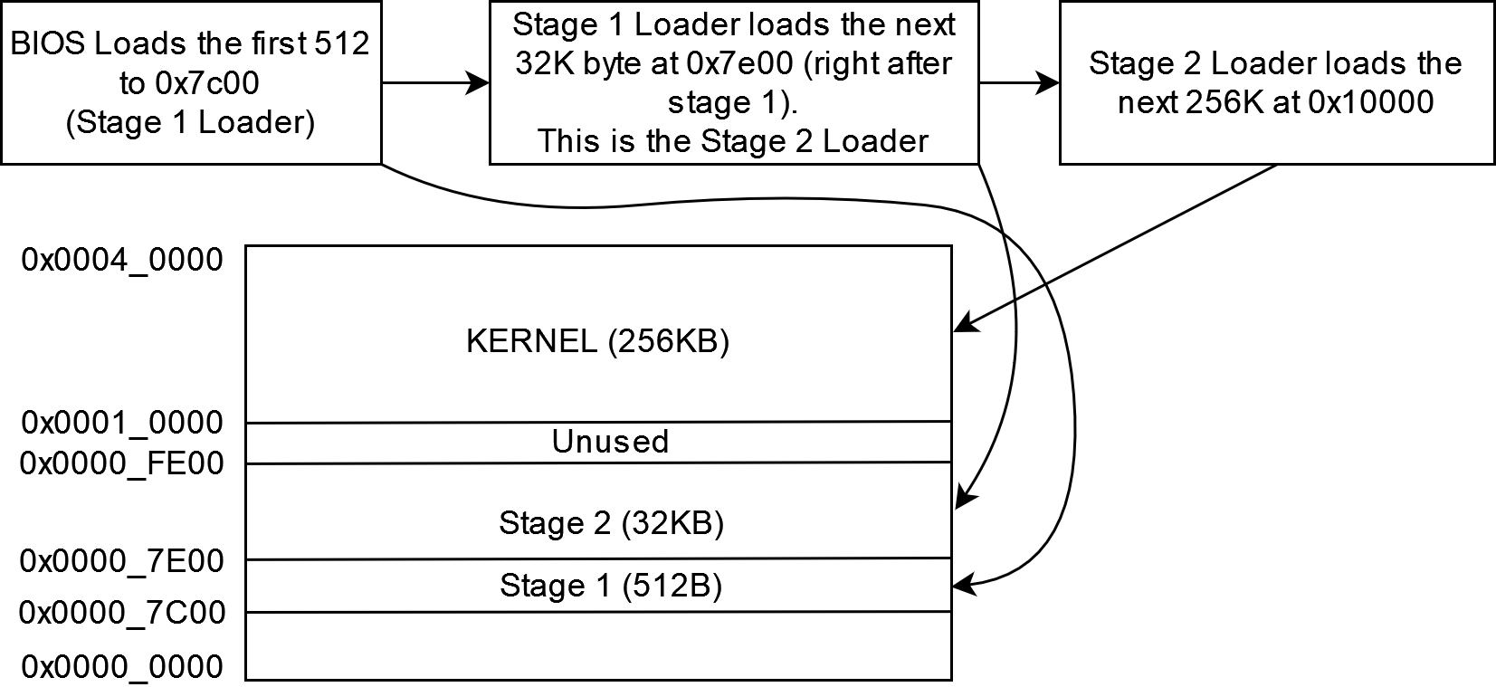
As we have mentioned before, x86 actually starts in “real mode” or “8086 emulation mode”, which is a 16-bit mode of operation. On boot, the processor and BIOS will load the first 512 bytes (first sector) of our boot disk (the MBR region or the “boot sector”) to linear address “0x7c00” and starts execution from there. At the point of control transfer (CPU handing control to your program) it is guaranteed that
- The CPU is in real mode (16-bit). and
- Register
DLcontains the “drive number” of the bootdisk. (More on this later when we load the kernel)
As you can see, the BIOS will only load the first 512 bytes off the hard drive and our kernel is unlikely to be only 512 bytes large. This means we will first need a small program to load our kernel. This is one of the few times in this series we will do a little bit of “future proofing”. We will eventually want the kernel binary to reside in a file system, and no matter how simple, an implementaion of a file system is unlikely to fit inside the 512 Byte boot sector. So this means we will need an “intermediate” bootloader that will parse the file system, find and loads the kernel itself.
For simplicity we made some assumption:
- The kernel will be relatively small, less than ~256K.
- The “intermediate” stage of the bootloader will be less than 32K in size.
Note that these numbers are relatively arbitrary, and are fairly reasonable numbers for a simple kernel. (For reference, Linux kernel is only about 2MB in size) The goal here is that with small sized stuff, we can load the “intermediate” loader and the kernel fully into “low memory” (anything below 1MB).
Stage 1 Bootloader
As we have mentioned before, the stage 1 bootloader exists because of the 512B bios size limit. So we will be writing assembly and keep the code size small. Although the good thing is, in this section, we only need to do some simple setup work and call a few BIOS routines to help us load the stage 2 bootloader.
At power up, BIOS will load this code (512B) at memory location 0000:7C00, so
we will need to setup our linker to link the code at that location.
One thing to note here is that within a linker there are two kind of address exists for code and data, one is Link Address and the other is Load Address. Link address is where do we expect the code to be executed at, where as Load Address specifies where the code will be loaded to. (In our case, we can think of the Load address as the offset from the start of the binary that will be produced). This might not make sense yet, but as we move forward with the first linker script it will make more sense.
“Hello World”
Let’s get started by writing the simpliest program, and use this to test that we are able to produce a binary that gets linked and loads correctly into our emulator (either Bochs or QEMU or anything you prefer).
The first step would be writing our assembly code. We will be using the intel syntax in this blog. (You can look up the difference between intel and at&t syntax, notably the order of source and destination operands are reversed for the two syntax) Also we assume you have gcc for x86 installed. We will be using gcc for this tutorial, the sample code provided will use CMake as a build system. Although you are free to use whatever you prefer (such as Makefiles).
# set intel syntax with no prefix on register nor immediate
.intel_syntax noprefix

#
# We place the following code in the .text.init section so we can place
# it at a location we want using the linker script (0x7c00)
#
.section .text.init

# Set to 16-bit code mode. Since we are going to start in 16-bit real mode.
.code16
.globl start

start:
    #
    # This jump is not strictly necessary, but some BIOS will start you at 0x07C0:0000
    # which is in fact the linear address as 0x0:7C00, but the range of jump will be
    # different. We will unify that with this long jump.
    #
    jmp 0:true_start

.section .text

true_start:
    cli     # disable interrupts

    # We zero the segment registers
    xor     ax, ax
    mov     ds, ax
    mov     es, ax
    mov     ss, ax

    # Clear Screen and set video mode to 2
    mov     ah, 0
    mov     al, 2
    int     0x10

    # Print Hello World Using BIOS
    xor ax, ax
    mov es, ax
    xor bh, bh
    lea bp, hello

    mov ah, 0x13
    mov bl, 0x4 # red foreground
    mov al, 1
    mov cx, [hello_len]
    mov dh, 0 # y
    mov dl, 0 # x
    int 0x10

here:
    jmp here

hello: .ascii "Hello World"
        .byte 0
hello_len: .word $-hello
This can be assembled using the following command
gcc -c -m32 -static -fno-builtin init.s -o init.o
You can view the disassembled output (of any ELF) using objdump. objdump is
a tool that is very useful to view various information inside an ELF file. -D
here specifies disassembly.
objdump -D init.o
init.o:     file format elf32-i386
Disassembly of section .text:
00000000 <start>:
   0:   fa                      cli
   1:   31 c0                   xor    %eax,%eax
   3:   8e d8                   mov    %eax,%ds
   5:   8e c0                   mov    %eax,%es
   7:   8e d0                   mov    %eax,%ss
00000009 <here>:
   9:   eb fe                   jmp    9 <here>
Now that we have some code written, we can use a linker script to help us place the code at correct location and produce a binary that we can boot from. In addition, our linker script will help us check and ensure our code + data combined in the stage 1 bootloader does not exceed 512 bytes.
I have provided a linker script here, it is not very important right now, but if you are interested you can always learn more about linker scripts at GNU LD documentation here.
/* Linker Script for the Stage 1 Bootloader */

/*
 * we use this "boot" memory region to make sure we throw an
 * error if we ever go over 512 bytes in the 1 stage binary
 */
MEMORY {
    boot : ORIGIN = 0x7C00, LENGTH = 512
}

ENTRY(start)
SECTIONS {
    text 0x7C00 : {
        *(.text.init)
        *(.text .text*)
    } >boot
    .rodata : {
        *(.rodata)
    } >boot

    .bss : {
        *(.bss)
    } >boot
    .data : {
        *(.data)
    } >boot
    /DISCARD/ : {
        *(.debug*)
    }
}
We can link using the above linker script like this
ld -m elf_i386 -N -T stage1.ld -o stage1.obj init.o
Almost there, we now have a single file containing our code assembled and linked at the correct location. We are one step away from being able to boot this code. The only thing is that this code is currently in ELF format, which the BIOS does not understand. We will need to extract only the code and data portion from this ELF and produce a disk image that QEMU can boot from.
We can copy all the data from ELF to a binary file using objcopy.
objcopy -O binary stage1.obj stage1.bin
We can now build a disk image and run QEMU with it.
qemu-system-x86_64 -m 512 -drive file=guideos.img,index=0,media=disk,format=raw
By running this code, you should see hello world printed in red on screen.

Congratulations, you have just wrote your first bootable binary on x86! Everything up to this point can be found here along with a CMake project setup for your convinence. We will continue from here next time and finish our stage one loader as well as setup a bare bones empty loop for our stage 2 loader.
Notes
Installing QEMU on Ubuntu 20.04
sudo apt install qemu-system-x86
WSL and GUI
if you are using WSL or on Windows, you might be interested in setting up
an X-server so you can use GUI applications like qemu-system-x86.
https://aalonso.dev/blog/how-to-use-gui-apps-in-wsl2-forwarding-x-server-cdj
or if you are on Windows 11, WSLg might be of interest too.