Keyboard Hacking - TEX Yoda II (1) HW Analysis
Hardware Keyboard Reverse Engineering HT32
Recently someone on reddit sent me a TEX Yoda II keyboard. It is certainly an interesting board. Not only it is a 60% which greatly saves desk space, it also integrates a IBM style “trackpoint” so you can put away your mouse too.
Unfortunately the firmware that came with the board is really boring and lack some
features that I think is really needed to make a 60% keyboard work. Such as having
layers that can be put into a lock mode, or having my typical caps becomes ESC and
also act as a layer trigger so I can have arrow keys overlay onto the h j k l
keys. (VIM Binding)
So the idea is to port a popular keyboard firmware: QMK onto it.
As with all my QMK ports before, it all starts with reverse engineering.
Upon first inspection, we can see all the chips are on the back of the board. And none of them are covered in black goo. Beautiful. Among them we can see
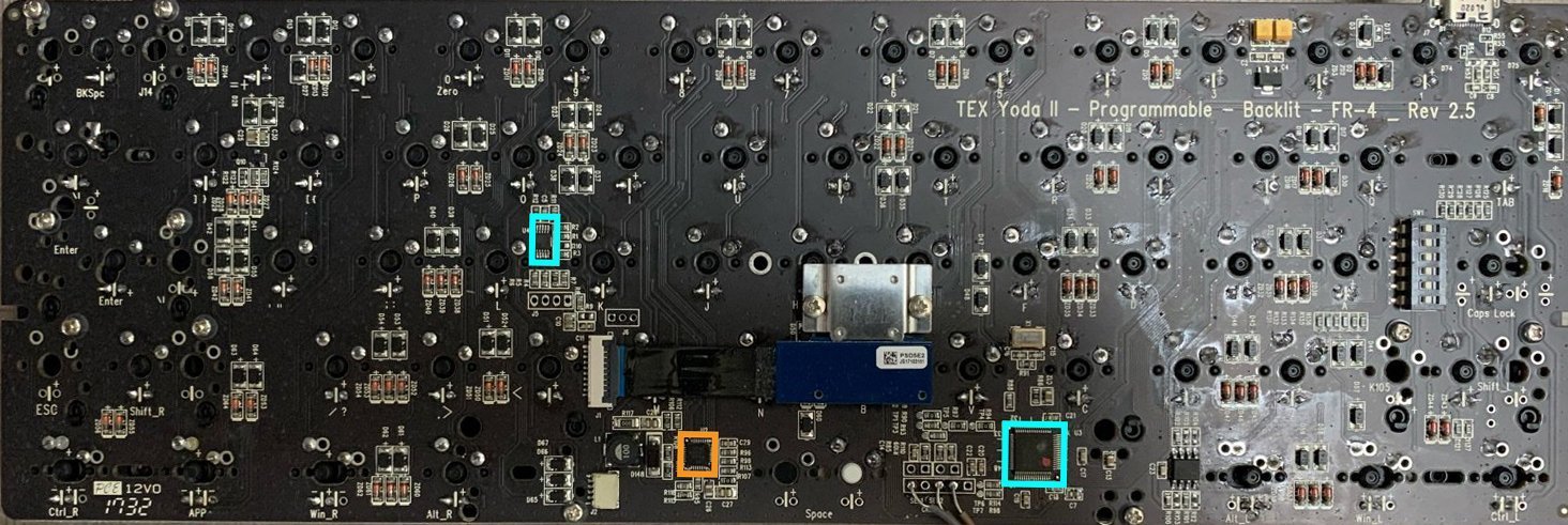
HT32F1654- (Blue Bottom) Main MCU , ARM Cortex-M3 from Holtek. This is very commonly used in keyboardsTPS61195- (Orange) A LED (strip) Driver Chip from TI.SN8F26E611L- (Blue Top) This is the tiny chip on top of the trackpoint connector. It is a 8-bit MCU. (This is a TSSOP-10 package with hard to see markings, we will come back to this later)
Initial Thoughts
At first glance, the turns out to be SN8 MCU chip did not look like a micro-controller to me, since with the small packaging, I assumed it is some kind of level shifter, since the markings are really hard to read.
Just from looking at this board layout, I assumed that the HT32 does the matrix scanning as well as polling data from the PS2 trackpoint use a software bit-banged protocol. Just as I was trying to map out the connection from the trackpoint connector to the HT32, I started to realize one important thing: None of the connection goes to the main MCU. It also seems to have its own power rails, also at ~3V.
With some probing around and looking at the traces, I found that all the PS2 connections goes to that small TSSOP-10 chip. So I started trying to search for what it is. Despite looking under a microscope at various angles, I was only able to tell it is a “SN8”.
From my recent work on the Kemove Snowfox, I was able to recall this SN prefix
is probably some SONiX micro-controller. So went on their website, and luckily,
the only SN8 controller they have in a TSSOP10 package is the SN8F26E611L.
Compare the pin map, VCC and GND all seems to be at the correct location.
So this confirms the chip is in fact a SN8F26E611L 8-bit micro-controller.
Track Point Communication
Now that we know there’s another controller that is polling the track point data we need to figure out how is this communicated to the main MCU, which eventually converts it into USB HID data so the computer could recgonize the mouse actions. We can see 3 connections from this 8-bit micro to the main MCU, and looking at the pin function assignments, 2 of those GPIOs are assigned UART Rx and Tx. It is natural to assume the communication is some kind of serial comm. With that I connected my logic analyzer, hoping to capture some startup initial setup data.
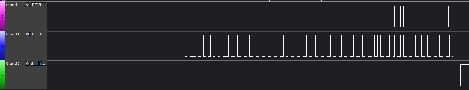
And oh boy was I wrong, the data oh the wire does not look anything like UART. There is no possible way for UART/RS232 data to look like this. This is clearly some kind of synchrous communication going on. Since the bottom trace looks too much like a clock.
SPI?
I begin to suspect this is some kind of a strip down version of SPI, since the SN8 has native SPI capabilities. So the 3 connections would be data, clock, and data in the other direction. However, did some longer captures, found that the third channel only toggled once since power up, it was low for the first burst of data, then it remained high. So this didn’t really make a whole lot of sense to be SPI.
Could it be I2C?
Closely inspect the start of each burst, we can see Channel 1 always goes to low right before Channel 0. If this sounds familiar to some of you, that’s right, this is exactally how I2C master signaling control of the bus. When we set CH0 as SDA, and CH1 as SCL, sure enough the bus got decoded as I2C perfectly.
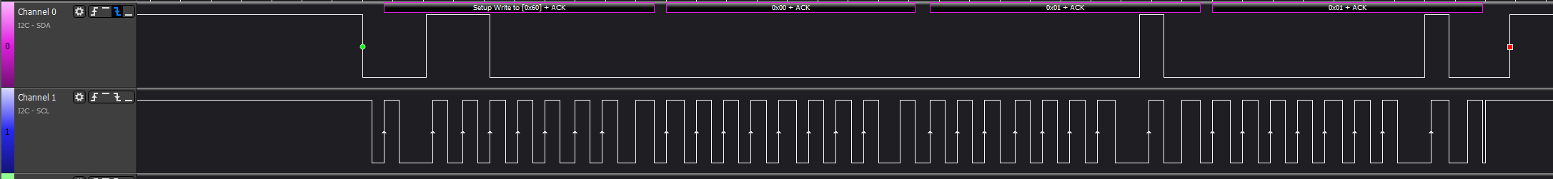
The only question left here is how dose the SN8 perform I2C when the datasheet claims no support of I2C at all? Bit-bang, of course. This looks like a software emulated I2C. The above capture is a comunciation where the SN8 is the bus master. (triggered when moving the trackpoint) As you can see, when the SDA goes from low to high, the clock slows for a cycle. This is a good indication that some bit-bang is happening, since the CPU has to probably takes a different (longer) branch for a L-H transition.
What’s next?
Since it is unlikely to be able to extract the SN8 firmware without buying some specialized tools (SN-Link), we will have to start the reverse engineering effor by attempting to extract the HT32 firmware. (Hint, Readout Protection is On) Luckily TEX provided a firmware update package that should contain the firmware.